 Biography
Overview
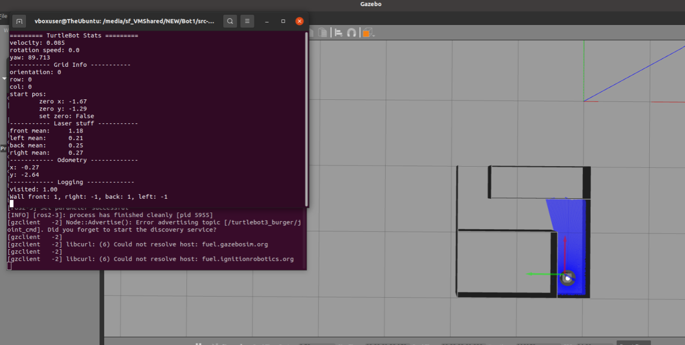
MazeTurtle programs a TurtleBot3 to explore an unknown grid-based maze, build an internal map as it goes, and then return to the starting cell using only that map, with no live LiDAR on the return trip. Built by a team of 4.
The robot's entire behaviour is modelled as a hierarchical statechart built in Itemis CREATE and compiled to Python, which runs on the robot through ROS 2. This keeps the decision-making logic cleanly separated from the control infrastructure.
System Architecture
A ROS 2 node (TurtleBotNode) subscribes to the LiDAR scan, odometry, and IMU topics and publishes velocity commands. The top-level orchestrator (main.py) feeds each cycle of sensor data into the compiled statechart, which holds all of the logic and writes back speed and rotation outputs.
Three Operating Modes
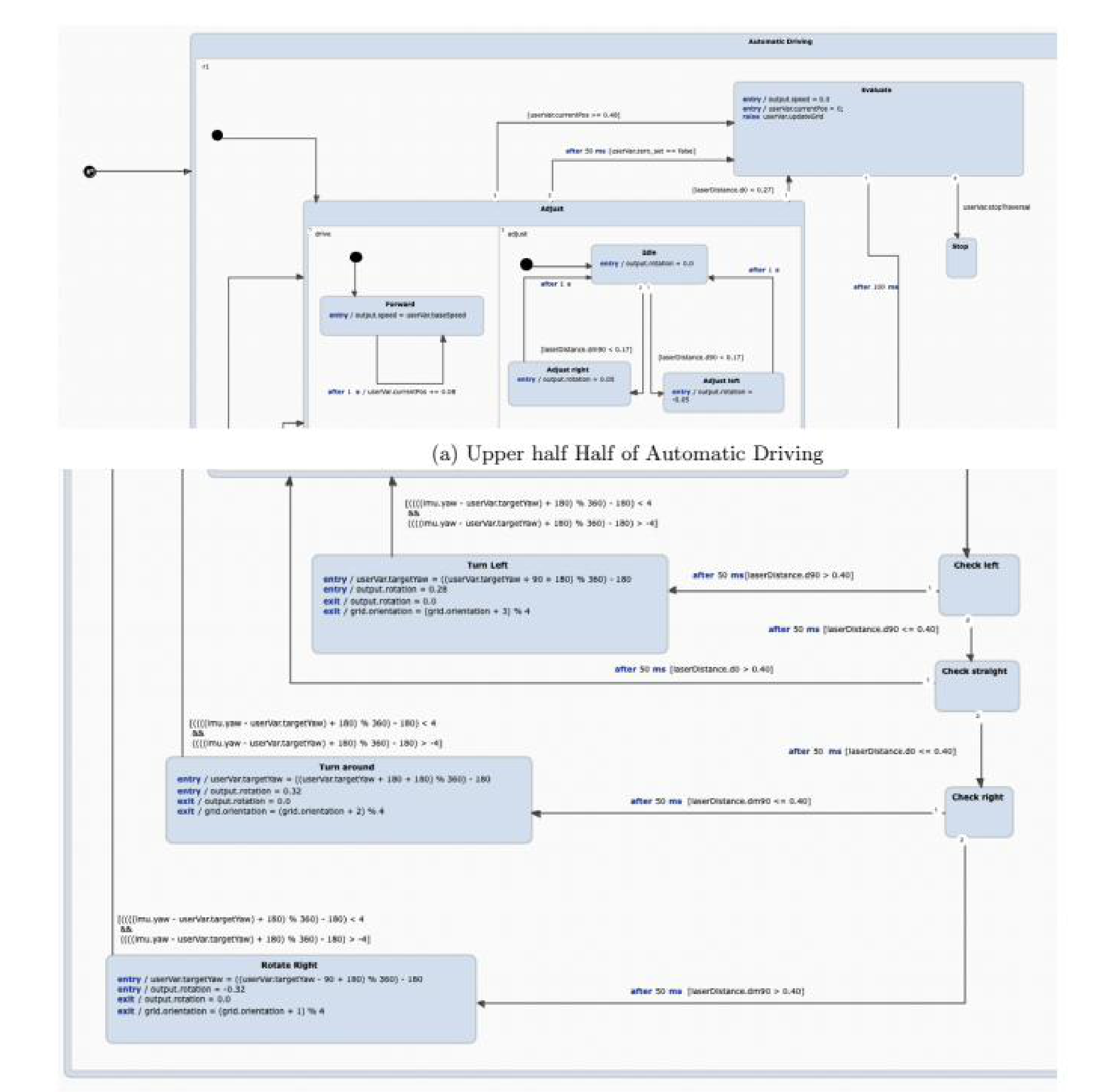
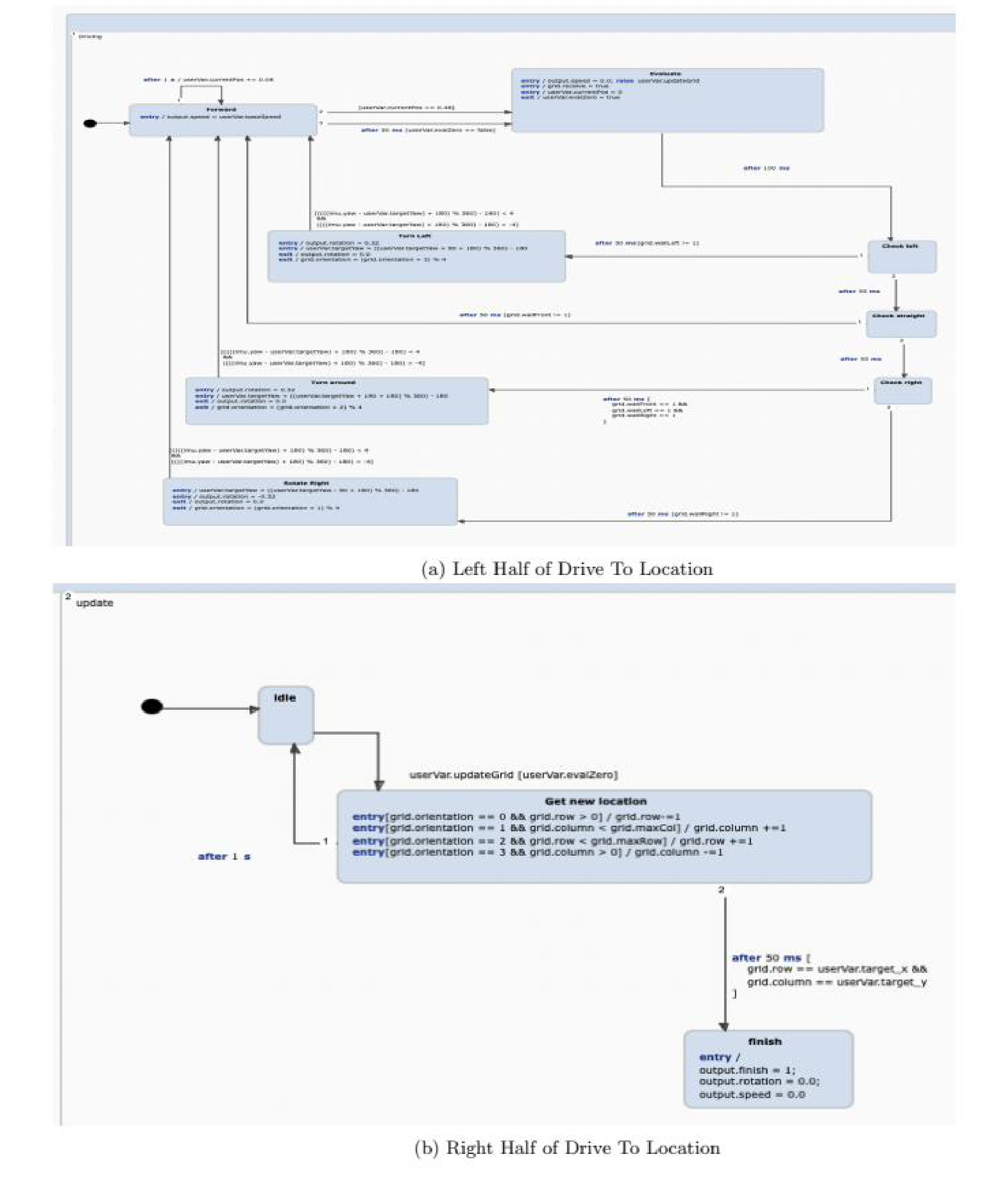
The statechart is organised around three modes the operator can switch between. Manual Control drives the robot by keyboard to position and calibrate it. Autonomous Driving explores the maze and maps it. LiDAR-less Drive to Location navigates back to a target cell using only the stored map.
Exploration Logic
At each cell the robot scans in a fixed priority order. It checks left first (open if the d90 distance is greater than 0.40 m), then straight ahead (open if d0 is greater than 0.40 m), then right; if none are open, it turns around. A separate adjust routine keeps the robot centred, nudging left or right whenever a side distance drops below 0.17 m, and a front distance under 0.27 m forces a new decision.
Rotation & Mapping
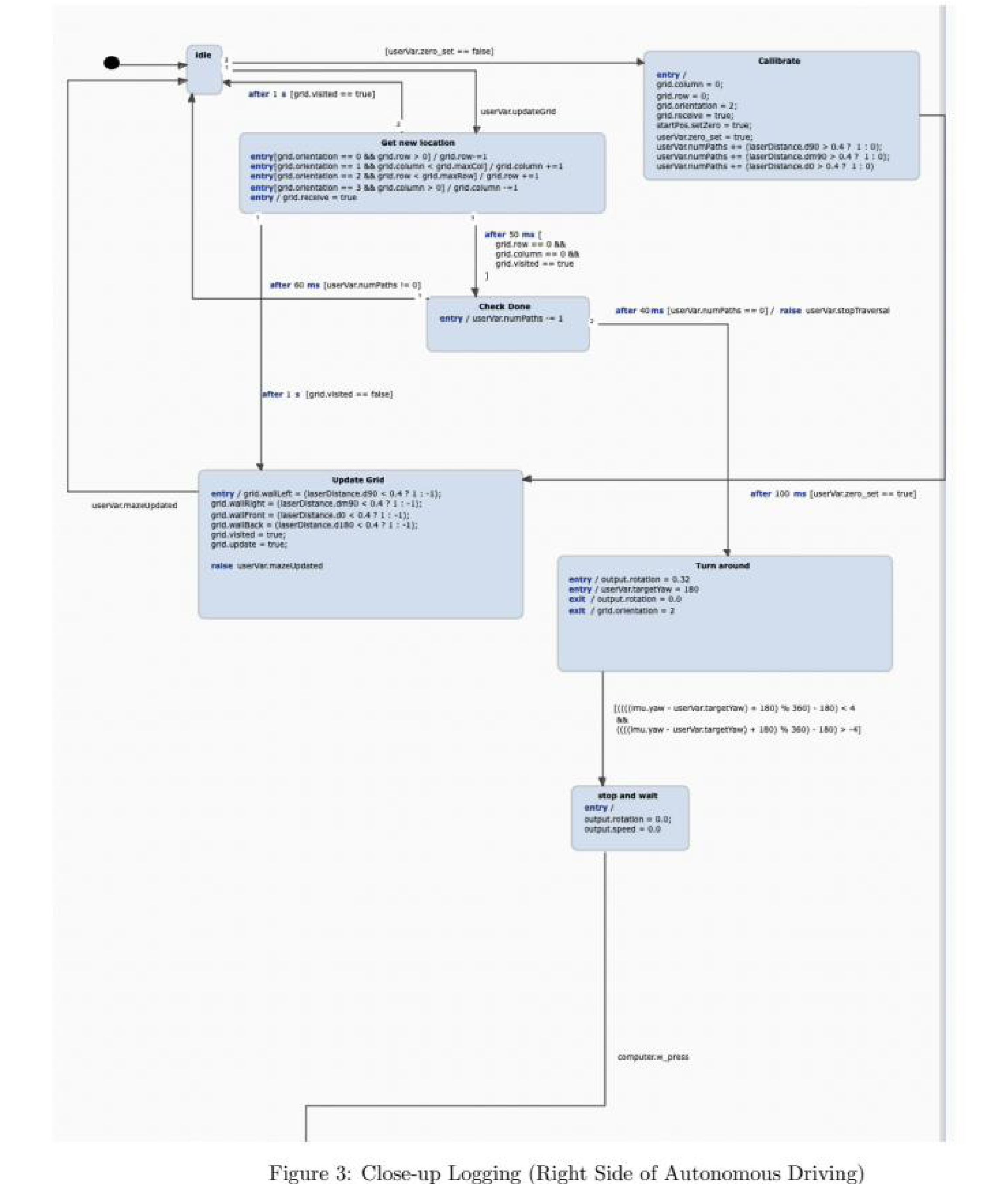
Turns are driven by an absolute target yaw rather than relative steps, so rotation error does not cascade across many turns. The robot transitions out of a turn once the IMU yaw is within ±4° of target. In parallel, a logging region records walls and the visited flag for each cell, which later becomes the sole input for the LiDAR-less return.
Reflections
Modelling the behaviour as a statechart kept the control logic separate from the ROS 2 plumbing, which made debugging manageable. The absolute-yaw approach proved reliable on hardware, where the robot rarely rotates an exact 90°.
My contributions: debugging, cross-platform testing on Windows and macOS, brainstorming the LiDAR-less navigation method, and writing the project report.
Overview
Frog Frenzy is a hardware game I built on an FPGA, rendered over VGA. A white frog crosses a gradient ocean while randomly spawned plants scroll toward it; the player jumps (btnU) or dives (btnD) to clear them, and each successful pass increments a hexadecimal score on the 7-segment display. It runs on real hardware with live video output.
System Architecture
A clock generator supplies the system clock and digit-select signal. Every button passes through a synchronizer first, since unsynchronized inputs were corrupting my state transitions. The heart of the display is a VGA Control module I wrote from scratch: it walks every pixel coordinate and emits the horizontal and vertical sync signals that separate modules for the ocean, frog, and plants then draw into.
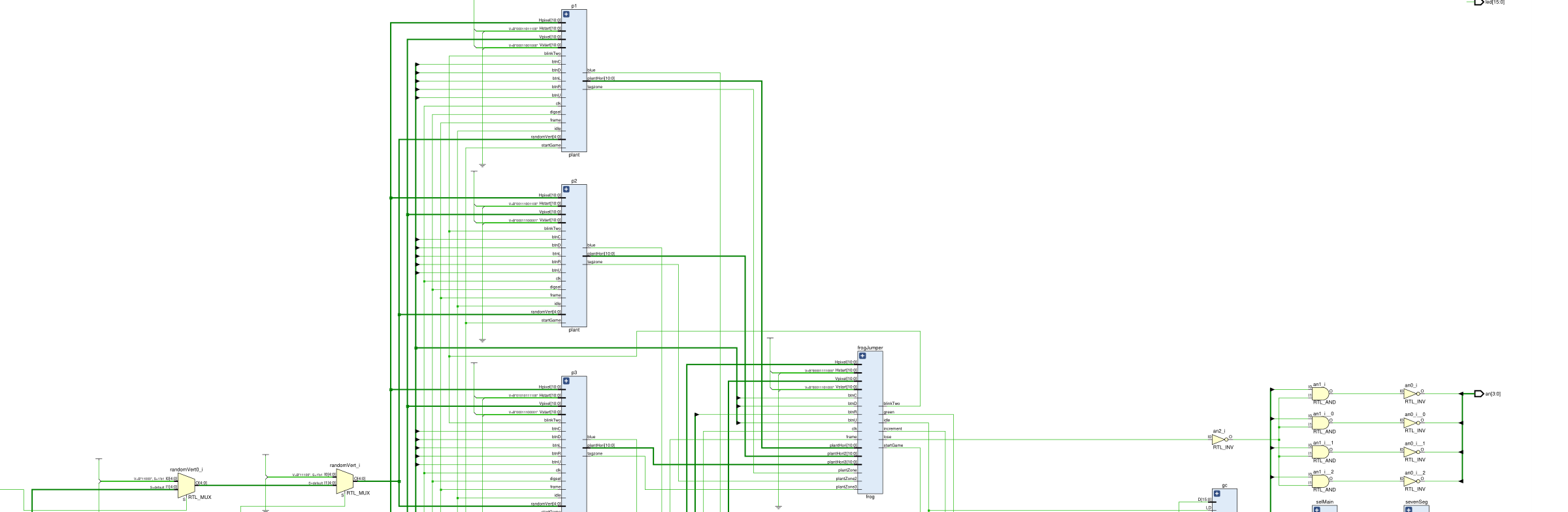
8-State Frog Controller
The frog runs on an 8-state machine (Idle, blinkTwo, Middle, Down, goUp, Up, goDown, Lose). Movement is frame-timed: a jump decrements the vertical position for 32 frames, then falls back for 32 more. A collision with a plant pushes the machine into Lose from any active state.
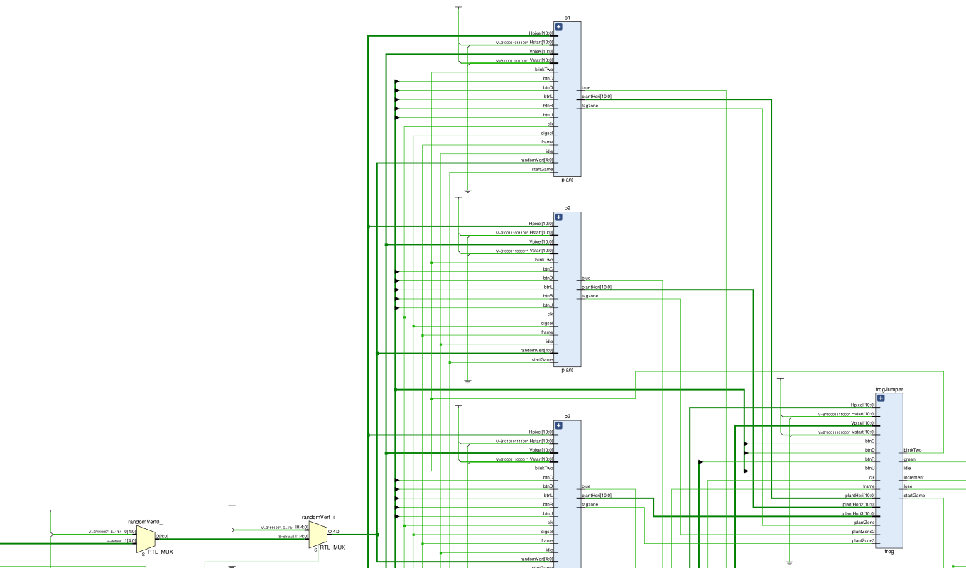
Randomized Obstacles
The first three plants are fixed; after that an 8-bit LFSR drives spawn positions. Reading it at unpredictable moments as it cycles through all 255 non-zero states gives each plant a fresh vertical offset, so the run never repeats.

Reflections
The hardest part was the VGA Control module: getting valid sync timing pixel-by-pixel left no room for error. Button metastability was the other trap, solved with proper synchronizers. Seeing the finished game run on a monitor, with the score climbing as the frog cleared plants, made the timing work worth it.
Overview
Turkey Counter is an FPGA project that tracks turkeys crossing a doorway using two IR sensors (modeled with btnL and btnR). A turkey moving right-to-left increments a signed counter; left-to-right decrements it. The running total shows on the two rightmost 7-segment digits, the sign is rendered as a dash on a dedicated anode, and while a sensor is blocked the leftmost digit counts seconds from 0x0 to 0xF.
Directional State Machine
The core is a seven-state machine (Begin, leftCount, rightCount, leftFinish, rightFinish, leftFinal, rightFinal). Direction is inferred from the order the two sensors break and clear: entering from the right path arms an increment, the left path arms a decrement, and the count only commits once the crossing fully completes. This ordering is what lets the machine tell a left-to-right pass from a right-to-left one.
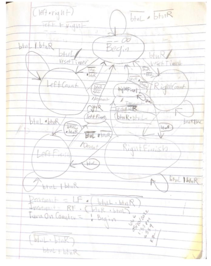
Signed Counting
I built the signed total from two unsigned gameCounters, one positive and one negative, wired so that an increment counts one up and decrements the other. A second small state machine reads both counts and the terminal-count flags to decide whether the display sits in a positive or negative state, which selects the value shown and drives the dash for negatives.
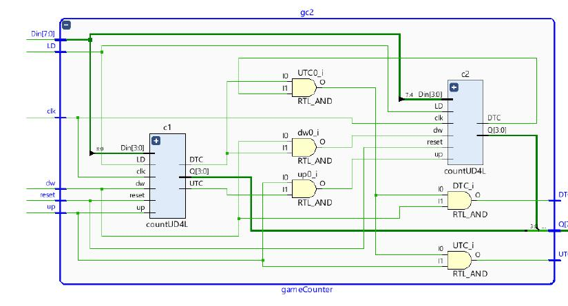
Simulation & Testing
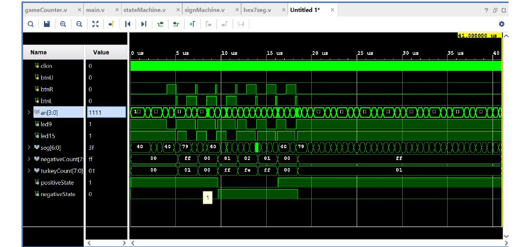
I verified the design in a testbench that drives the two sensors through full left-to-right and right-to-left crossings. The waveform confirms turkeyCount and negativeCount tracking together while positiveState and negativeState flip at the right moments, which caught the ordering bugs before they ever reached the board.
Reflections
The hard part was deciding when the machine should read as positive versus negative, since a signed value built from two unsigned counters has an awkward seam at zero. Splitting that judgment into its own sign state machine kept the logic clean. The project drove home the value of testing each module in isolation before composing them into the top level.
Overview
StopIt is a reaction game I built on an FPGA. Pressing btnC locks in a random target number on the left two 7-segment digits and starts a counter rolling from 0x00 to 0x3F on the right two digits. The player hits btnU to stop it, and the game compares the two numbers: a match is a win, which lights an LED and flashes both numbers together for four seconds, while a miss is a loss, which flashes the two numbers in an alternating pattern.
Game State Machine
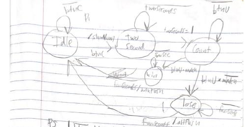
The game flows through five states: Idle, Two Second, Count, Win, and Lose. Pressing btnC moves out of Idle into a two-second lead-in, then into Count where the number rolls until btnU stops it. The stop result branches to Win or Lose depending on whether the numbers match, and each of those states holds for four seconds before returning to Idle. The state outputs drive when to show numbers, run the counter, and flash the display.
Random Number Generation
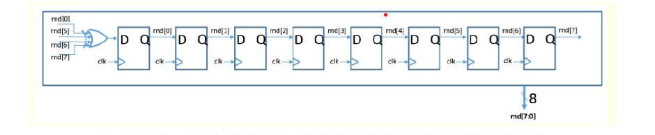
The target number comes from an 8-bit linear feedback shift register that feeds the XOR of bits 0, 5, 6, and 7 back into the first register, cycling through all 255 non-zero states. Because the register is free-running and only sampled at the instant the player presses btnC, the captured value is effectively random. I masked the top two bits so the target always lands within the counter's 0x00 to 0x3F range.
Simulation & Testing
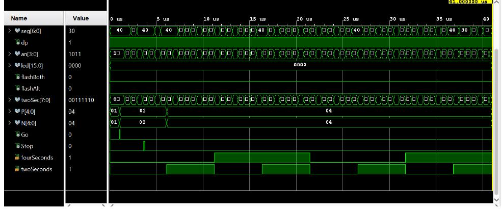
I verified the design in a testbench that presses btnC to start, lets the counter roll, then presses btnU to stop. The waveform confirms the present and next state buses stepping through Idle to Two Second to Count, with the two-second and four-second timer flags rising on schedule and the segment outputs reflecting the displayed numbers. Watching the state transitions line up with the timers is how I caught timing mistakes before loading the board.
Reflections
The trickiest part was the anode logic. With four digits that each need to be solid, off, flash together, or flash alternately depending on the game state, the active-low control conditions took real care to get right. Driving the flashing from a bit that toggles every quarter second kept the timing readable. The project cemented how a clean state machine can coordinate several timers and display modes at once.
Overview
Laboratory 8 was a breadboard logic build using integrated circuits that provided NOT, NOR, and NAND gates. Reading the datasheets to determine where to apply VDD and GND, I built two circuits: a 9-inverter ring oscillator to measure propagation delay, and a positive edge-triggered D flip-flop wired from NAND gates.
Breadboard & Power Setup
I powered the board from a 5 V supply, with a fuse linking the supply voltage to the positive column to protect the circuit and a wire tying the supply ground to the negative column. From there I worked off the datasheets for each IC to place Vcc, GND, and the signal pins correctly.
Ring Oscillator
Using the SN74LS04N inverter IC, I chained nine inverters so the ninth output feeds back into the first input, leaving the loop with no stable state so it oscillates on its own. I probed it with the oscilloscope on Channel 1 in DC mode and used cursors to measure a 150 ns period, then divided by nine to get a per-stage propagation delay of 16.6 ns. The waveform came out as a square wave that resembled a clock signal.
NAND-Gate Flip-Flop
The harder build was a positive edge-triggered D flip-flop made from SN74LS00N NAND gates. The main challenge was that the design needs a 3-input NAND, which the chip does not provide, so I composed one by chaining gates: feeding the clock and the output of NAND 2 into NAND 5, then feeding that result and the output of NAND 4 into NAND 6. A manual switch stood in for the clock to simulate edges.
LED Verification
To confirm the flip-flop latched and held a value, I wired three LEDs: yellow for the D input, green for Q, and red for !Q. Each LED's anode connected to the IC input and its cathode to ground through a 2.2 kΩ resistor, sized from the current equation to keep current under 20 mA. Flipping the switch while feeding a high D held Q high, lighting yellow and green together.
Reflections
Working straight from datasheets, with no abstraction between me and the silicon, made the timing real in a way simulation never did: a 16.6 ns delay is invisible on paper but it is what makes the oscillator run. Composing a 3-input gate by linking three NAND gates was the moment the lab clicked, building the primitive I needed out of the ones I had.
Overview
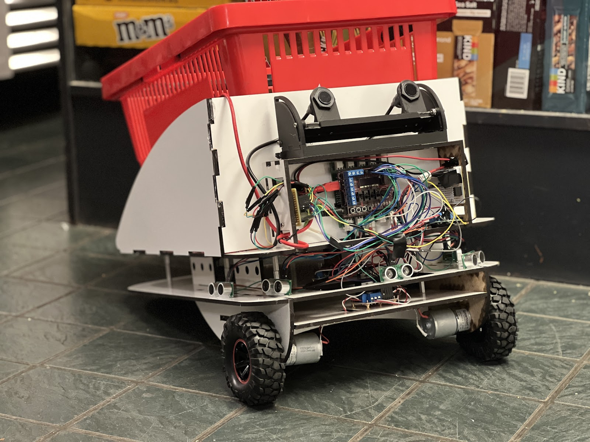
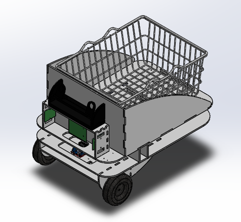
The Following Basket is an autonomous cart that carries a user's belongings and follows them on foot through stores, warehouses, and outdoor spaces. The user holds an IR beacon and pairs over Bluetooth Low Energy; the cart tracks the beacon, drives itself to stay behind the user, and avoids obstacles along the way. Built over two quarters by a team of 6.
System Architecture
Two microcontrollers split the work. A ChipKit Uno32 runs the drive base: it reads the sensors and drives two DC motors through an H-bridge, using PWM on two pins for speed and a pair of pins per motor for direction. An Arduino Nano 33 BLE owns the user link, holding the BLE connection to the phone app and relaying proximity data to the Uno32 over I2C. Both were written in C++ in the Arduino IDE.
Behavior State Machine
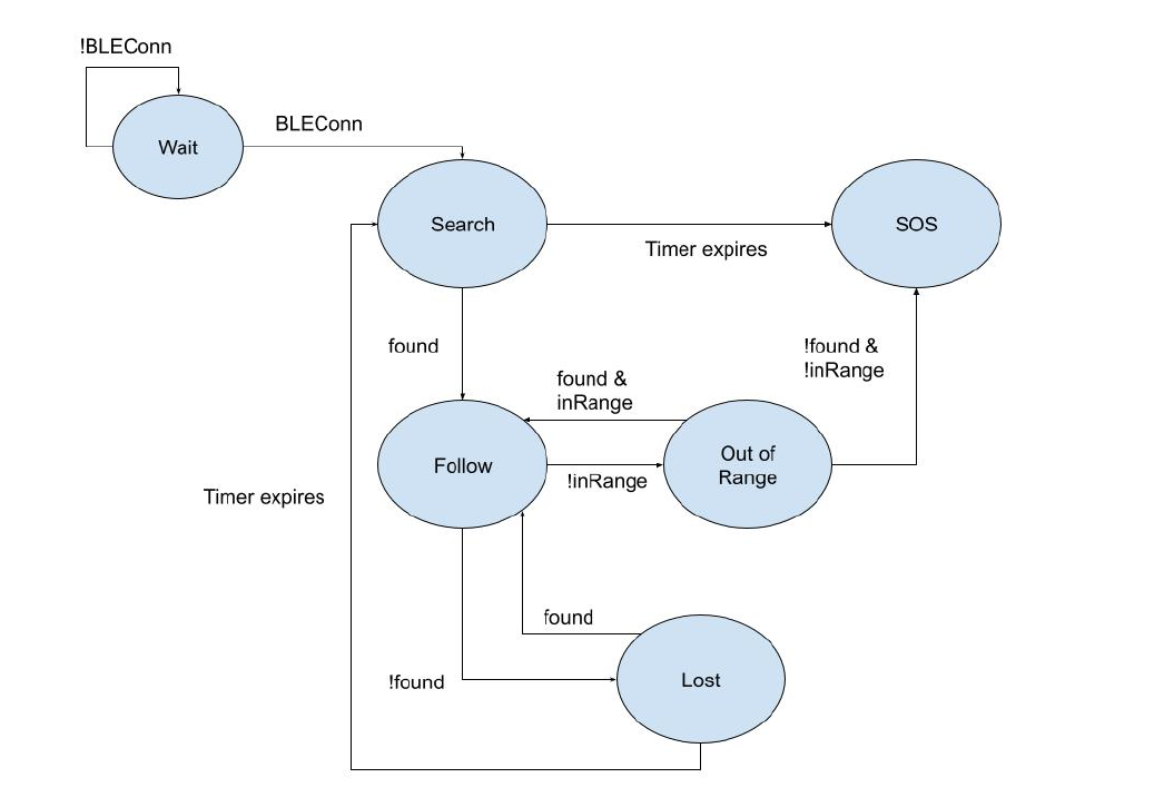
The whole system runs as a hierarchical state machine. The cart powers on in Wait until a BLE link is made, spins in Search until the beacon is found, then enters Follow. From there it branches into Out of Range when the user pulls away, Lost when the beacon drops out, and SOS when it cannot recover, sending a BLE alert to the user's phone.
Beacon Tracking & Object Avoidance
Two DFRobot IR camera detectors give a combined 66 degree horizontal field of view and report x-y coordinates of the user's beacon over I2C. When the beacon crosses a left or right threshold the cart tank-turns to recenter it; otherwise it drives forward. Five ultrasonic sensors cover a 180 degree arc out to 4 meters, with a sliding average to reject noise so a single bad reading does not trigger a false avoidance maneuver.
Proximity via RSSI
The original plan used three Arduinos to triangulate the user from RSSI, but the values proved too noisy to locate a user reliably indoors. We simplified to a single Arduino and a robust binary in-range check: a Kalman filter cleans the raw RSSI, values are compared against a -70 threshold, and a 10-element boolean array decides out-of-range status only when most samples agree. That trade gave a measurement we could trust at 6 meters.
Aesthetic Design & Reflections
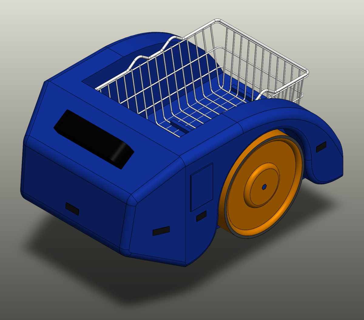
Alongside the working prototype we modeled a production concept in SolidWorks, with a modular body meant to ship preassembled and come apart for maintenance. The render below shows that target form.
My contributions were on the software side: BLE communication between the user and the basket, and gathering and filtering the RSSI values used for distance. The hardest problem was RSSI positioning; with better hardware (a UWB-capable board) we could have located the user properly rather than settling for an in-range flag.
About Me
Hey there! I'm Maxim, an Embedded Systems Engineer who specializes in cyber-physical systems and real-time control. I'm passionate about working at the intersection of hardware and software to bring complex, autonomous projects to life.

My Academic Journey
My engineering journey began at the University of California Santa Cruz, where I completed my Bachelor of Science in Computer Engineering. Currently, I am based in the Netherlands, pursuing a Master of Science in Software Engineering at Universiteit van Amsterdam.

Cyber-physical Systems
Contributed to MazeTurtle (team of 4): a hierarchical statechart built in Itemis CREATE to control a TurtleBot3 for autonomous maze exploration, with a return trip that relies only on the internally built map rather than live LiDAR. Worked on debugging, cross-platform testing, and the LiDAR-less navigation approach, all running through a ROS 2 integration layer in Python.
Embedded Sensing & BLE
Through a hands-on embedded systems course, I built up the PSoC 6 microcontroller from blinking LEDs to I2C sensor interfacing and exposing distance and speed measurements over Bluetooth Low Energy, then carried the same ideas onto an Arduino Nano 33 BLE. The work leaned heavily on reading datasheets and API docs rather than step-by-step instructions.
Hardware & Logic Design
Engineered a "Frog Frenzy" FPGA Game with VGA functionality, using an LFSR for random obstacles. Also constructed physical breadboard circuits with SN74LS series ICs, including a 9-inverter ring oscillator (16.6ns delay).
Fostering the Next Gen
Coding Instructor at Coding Mind Academy since July 2024. Formulating practical courses in Raspberry Pi, Micro:bit, and Lego Robotics for K-12 students using Python, C++, and Unity.

LN 1, Col 1
Windows (CRLF)

Local Security Restriction
Due to browser security policies under the file:// protocol, local PDF files cannot be embedded inside the window.
Please run a local web server (e.g. python3 -m http.server) or click Download / Open In New Tab above to view the document.
Ready
100%
12:00 PM